Customize Measurement Types
Current AlignPlus version only provides three measurement types: point to point, point to line, and line segment to line segment. If a user needs other types of measurement, such as circle to circle, blob to blob, he/she can customize them by creating VisionPro toolblocks following the input and output requirements listed below.
Input Requirements
| Inputs | Type | Description |
Necessity |
|---|---|---|---|
| InputImage | Cognex.VisionPro.ICogImage | To receive the input image from a camera | must have, must keep the input name |
| Input1 | Decided by user | The first element of measurement input | must have, must keep the input name |
| Input2 | Decided by user | The second element of measurement input | optional, can be exempted if the toolblock is not to measure between two features |
| LabelAngleInDeg | Double | Result label display angle on image display in degrees | must have, must keep the input name |
Output Requirements
The outputs of custom toolblock can be named differently depending on user's preference, such as "d", "X", "Y", etc. These outputs names would be available in the "Measurement Source" column of a tolerance check on AOI Setup HMI for the user to select which value to check if the measurement type were the user customized type.
Users can also specify on how the measurement graphics should be displayed on image display through customizing "OutputGraphicCollections" output.
The requirements for the OutputGraphicCollections output are as below: it must be a Dictionary<String, Cognex.VisionPro.CogGraphicCollection> type of object, in which the key strings in the dictionary must come from the names of the other outputs, such as "d", "X", "Y", so that when the inspection task uses these graphics, it knows which output values the graphics belong to. However, users does not need to create graphics for all output values, the inspection function will automatically generate graphics for values who does not have the corresponding graphics in OutputGraphicCollections output.
Example of custom measurement type
Here is an example of a customized circle to circle measurement toolblock. For detailed information about how this toolblock is configured, please open "PointPoint.vpp" under "C:\ProgramData\Cognex\Designer\Plugins\Cognex\AlignPlusTemplateApplication\Data\Vpp" for reference.
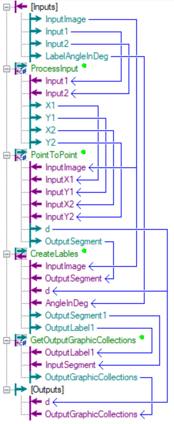
After the custom toolblock is created, save it to the following path: "C:\ProgramData\Cognex\Designer\Plugins\Cognex\AlignPlusTemplateApplication\Data\Vpp". Here the name of the custom toolblock is "CircleCircle".

In the run mode of AOI inspection application, find two circles in its features finder and save the configuration to the alignment recipe.
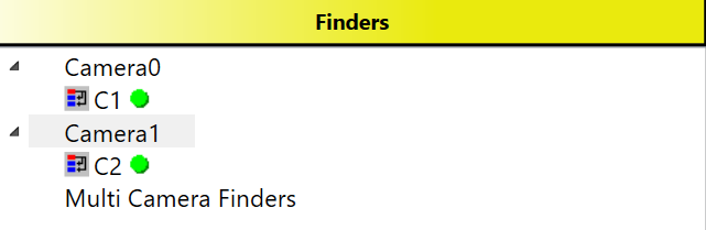
Reboot Cognex Designer to load the newly added VPP files for the AlignPlus application. After that, you should be able to find the "CircleCircle" in Measurement Type options on the AOI Setup page. Select the two circles added in last step as the Input1 and Input2, and click "Apply" to confirm.
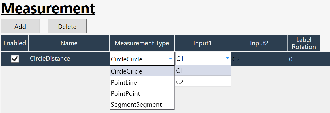
After the circle to circle measurement item is added. Its output "d" is available for users to select as the Measurement Source of a tolerance check.
